|
Bus
Air Filter Versions
|
|
|
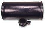
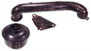
Late'49-Late'53,
except
Pickup and Ambulance
This
air cleaner is often referred to as the "coffee can"
air cleaner. This style cleaner has 10 holes located on the
left side, which allowed for an intake of air. The inner cylinder
was packed with hair material, which was to be soaked in degreasing
cleaning solvent, dried and moistened with SAE 20 engine oil.
Mann was the manufacturer of this particular filter. Knecht
made another style and was available as an option and intended
for dusty regions. This air cleaner was cylindrical in design,
and had 2 intake slots located in the housing. This air cleaner
is comprised of two halves, which were held together by 2
spring clips. When separated, an internal filter could be
easily cleaned, then reinstalled. |
 |
|
|
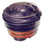
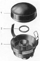
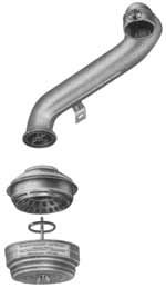
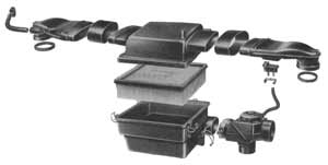
Late'53-Mid'55,
except Pickup and Ambulance
This was the start of the oil bath style air
cleaner as standard equipment for VW. This particular cleaner
was installed intermittently along with the "coffee can"
style filter, starting in late 1953. This air cleaner featured
an upper and lower hemisphere, with the upper hemisphere being
secured to the lower by means of a metal strap. The lower
chamber of the filter was to be filled to an inscribed mark
with SAE 20 engine oil. The upper portion housed a fibrous
material, which was to be soaked in degreasing solvent, dried,
then moistened with SAE 20 engine oil. This was the first
oil bathed filter that was available for VW's. The oil bathed
filter functions by extracting dust and dirt by means of pulling
heavy particles downward within the lower chamber, and trapping
them within a pool of oil. The oil bathed filter also served
as an air intake noise damper. The late'53 strap style air
filters were made with one minor flaw (see lower photo) in
that the upper portion lacked a lip, which allowed moisture
to flow into the lower chamber. The 1954 design included this
lip and thus cured the water infiltration dilemma. This air
cleaner was used intermittently in 1953, thus there is no
chassis number for its birth. However, it was used through
Feb'55, ending with chassis number 20-117902 |
|
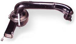
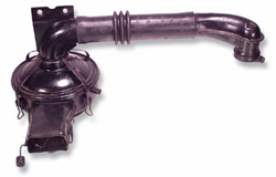
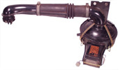
Mid'55-Mid'56
VW introduced an entirely new air cleaning arrangement.
This air cleaner was mounted remotely by means of a metal
duct. The air filter element portion is secured to the elbow
of the duct with a wing nut, which is secured to the base
of the filter element. |
 |
|
|
Mid'56
- May'59, 36 hp (Photo not available)
The filter element is secured by means of a fixed stud,
the wing nut was omitted.
|
|
May'59
- May'60, Bastard 40hp
Clamps are added to hold the two halves of the filter
element together. |
 |
|
|
|
May'60
- Sep'64(1965 model year), 40hp only
VW
introduced an entirely new air cleaning arrangement starting
with the May'60 model year. It featured a warm air intake
hose and a controllable flap valve. The controllable flap
valve, in the released position at temperatures under 67 degrees
Fahrenheit, is opened by means of an induction of air as the
the engine speed increases. The valve shaft is equipped with
a small weight for compensation purposes. In the fixed position,
at temperatures of 68 degrees Fahrenheit and higher, the air
intake tube is opened and the connection for the pre-heater
pipe from the left heater junction box is closed by the valve
simultaneously. Thus, this clever arrangement supplies warm
air at low engine speeds in an effort to prevent the formation
of ice inside the carburetor, particularly when the weather
is cold, and also helps with fuel conservation. |
|
1963
- Sep'63
with 1500cc option
The duct is re-worked a bit with the inclusion of a rubber
hose. |
 |
|
|
Oct'63-1967
The air cleaner assembly is now mounted on the right
hand side of the fan housing.
|
 |
|
|
|
|
1968-1970
Starting with this year the air intake flap regulates according
to engine temperature. The cold engine draws air from the
cylinder/head area where the engine warmth is created quickest.
This flap is regulated via a cable that connects to the
air flaps at the base of the fan shroud.
Also
incorporated was an additional flap that controlled the
fumes entering from the crankcase. At higher speeds this
flap is opened and fumes from the crankcase are drawn into
the intake system. This is one example of many pollution
controls that VW was implementing in 1968-1969.
1971
only
Starting with engine AE 0 000 001 VW incorporated a separate
thermostat located on the backside of the air filter assembly.
Incorporating a separate thermostat deleted the cable that
tethered the air filter assembly to the engine on prior
models thus allowing for a much simpler/quicker cleansing.
|
|
|
|
1972
only
The flap regulating intake air is now controlled by two factors,
engine load and air temperature being drawn in. This new system
responds quicker to engine operation conditions. Intake manifold
vacuum is routed through a thermostat, mounted to the air
intake of the air cleaner, into a vacuum servo mounted to
the air intake snout. This servo actuates a flap that controls
the intake of air flow, warm air from the head/cylinder area
or cool air from the engine compartment. |
|
1973-1974
and 1973-1979 engines without fuel injection
VW moved from the oil bath filtration system to the newer
paper element style. The housing is now constructed of plastic.
Intake air regulation is controlled using the same methods
described in the 1972 only above. |
 |